


 Фазлутдинов К.К
 03.12.2016 (updated 10.07.2023)
 63213 views
Mechanism and technology of anodizing An.oks. Structure and properties of aluminum oxide in the coating.
Content:
1. General information about anodizing (anodic oxidation) of aluminum.
2. The composition and structure of aluminum oxide in the coating.
3. Theories of aluminum oxide film formation.
4. Features of the growth of aluminum oxide during anodization.
5. Properties of oxide coatings on aluminum.
6. Sealing and coloring of anodic oxide films on aluminium.
8. Anodizing with ordered micropore architecture
1. General information about anodic oxidation (anodization) of aluminum.
The surface of aluminum and its alloys, due to their tendency to passivation, is permanently covered with a natural oxide film. The film thickness depends on the ambient temperature and is usually 2-5 nm. The corrosion and mechanical strength of aluminum can be increased by tens and hundreds of times by subjecting it to electrochemical oxidation (anodizing).
Anodizing — is the process of obtaining a protective oxide film from aluminum. It is produced by the electrochemical method in aqueous solutions. The density of such a coating is 2.9-3.8 g/cm3, depending on the production mode.
Purpose of the coating — protection of products against corrosion, increase in wear resistance, giving a decorative appearance (when filled with dyes)
|
Designation |
An.Ox — anodizing without additional requirements; An.Oks.nv — with filling in water; An.Ox.nkhr — with filling in chromate solutions; An.Ox.(dye color) — with filling in dye, example - An.oks.h; Ano-color — color anodizing obtained directly from the bath; An.Ox.tv — solid; An.Ox.eiz — electrical insulating; An.Ox.emt — enamel; An.Ox.emt. (dye color) — enamel filled with dyes, example - An.ox.emt.h; An.Ox.chr — anodizing from chromic acid electrolyte. |
|
Coating thickness |
6-40 microns (for An.ox.tv the thickness is higher). |
|
Microhardness (depending on the brand of aluminum alloy) |
1960-2450 MPa — D1, D16, V95. 2940-4900 MPa — A5, A7, A99, AD1, AMg2, AMg2s, AMg3, AMg5, AMg6, AMts. 4900 MPa — for enamel coating. |
|
Electrical resistivity at 18°C |
1012 Ohm⋅m |
|
Permissible operating temperature |
100° C (may increase when filled with dyes) |
Anodic oxide coatings are divided into the following groups:
- protective (9-40 microns) - requirements are made only for corrosion resistance;
- protective and decorative (9-40 microns) - not only corrosion resistance is important, but also appearance (colored and painted coatings can also be included here);
- hard (usually >90 µm) - first of all, increased surface microhardness is needed. They can also serve as electrical insulators);
- electrical insulating (40-90 microns) - the value of the breakdown voltage is estimated;
- thin-layer (up to 9-15 microns) - are used, as a rule, for painting, or to preserve the gloss of the surface after coating;
- ematol.
- coverings with combined properties.

Figure 1 — Metal anodizing. Example.
An.oks.tv — this is a hard anodizing of aluminum, which differs from the standard An.Ox coating in its high thickness and features of the deposition process. In some cases, the thickness of a hard coating reaches hundreds of micrometers, while in a conventional coating it is measured in tens. The high thickness and hardness of An.Ox.tv ensures unsurpassed wear resistance of the aluminum surface.
As electrolytes are used:
- Low aggressive phosphoric, citric, boric acid;
- Aggressive sulfuric acid, sulfosalicylic acid, chromic anhydride.
Metal anodizing always takes place at an increased voltage, most often from 12 to 120 V. Sometimes the voltage can reach huge values for electroplating - up to 600 V.
Reaction products released at the anode can:
- Completely dissolve (no coating forms);
- Create a tightly bonded thinnest (tens of nanometers) compact electrically insulating oxide coating on the metal surface;
- Partially dissolve in the electrolyte and form a porous oxide coating with a thickness of tens and hundreds of micrometers.
After application, the porous coating can be left "as is", compacted in water, or filled. In the first case, the coating is perfect for applying paints and varnishes and gluing. In the second, the coating retains its silver color and becomes more corrosion resistant. In the third case, the coating can be given color without applying paints and varnishes. More about this is written in section 6.
2. Composition and structure of aluminum oxide after coating.
Anodic coatings on aluminum can be thin non-porous and thick porous.
When thin coatings are obtained in weak low-aggressive electrolytes, an oxide is formed on the metal surface according to the reaction:
2Al + 3H2O - 6e → Al2O3 + 6H+
An illustration of the reaction is shown in Figure 2.

Figure 2 — Scheme of the formation of a thin oxide film in low-aggressive electrolytes.
All of these solutions work at the high temperature of 70 to 95° C required to boost the electrical conductivity of the solution and reduce the cost of electricity. Nevertheless, the voltage on the bath remains very significant - 150-600 V. The processing time is 15-30 minutes, and the thickness of the coatings does not exceed fractions of a micron. Due to the low porosity, thin anodic oxide coatings are poorly painted.
Thick, porous anodic oxide coatings are made from aggressive solutions (such as sulfuric acid). In coatings obtained from aggressive electrolytes, two layers are usually distinguished (Figure 3):
- A thin, non-porous barrier layer adjacent to metal (1) formed from a condition of 0.008 - 0.012 µm per 1 V of applied voltage, and is typically 0.01 - 0.03 µm.
- Thick porous layer (2), which is a system of cone-shaped pores penetrating the oxide film, and having a thickness of several micrometers to millimeters.

Figure 3 — Structure of aluminum oxide layers obtained from aggressive electrolytes.
Outline thick porous anodic oxide coating is confirmed by the results of electrochemical impedance spectroscopy (Figure 4).

Figure 4 — Bode plots for aluminum grade Al 6061, anodized in sulfuric acid electrolyte, followed by sealing in water by immersing them in 3.5% sodium chloride solution for the specified time. On the left is the Bode modulus, on the right is the Bode phase.
The following areas can be seen on the Bode module plots:
- High impedance values at ≤ 1 Hz clearly indicate the characteristics of the barrier layer of the anodizing coating.
- The quasi-horizontal area in the Bode modulus plot and the corresponding minimum area in the Bode phase plot characterize the resistance behavior of the porous layer.
- The steep part at higher frequencies in the Bode modulus plot characterizes the capacitive behavior of the porous layer.
Equivalent electrical circuit of porous anodic coating with sealing in water is shown in Figure 5.

Figure 5 — Equivalent electrical circuit of a porous anodic oxide coating with sealing in water: Rsol - electrolyte resistance, Ro and Co - resistance and capacitance of the outer crystalline layer, Rpw and Cpw - resistance and capacitance of the pore wall, Rp and Cp - resistance and capacitance of the pore body, Rb and Cb - resistance and capacitance of the barrier layer.
As for the composition of anodic oxide coatings, thin, non-porous films are mainly anhydrous aluminum oxide, which in its pure form is located at the border with the metal. From 0.6 to 20% boric anhydride (electrolytes with boric acid) is introduced into coatings of this type, as well as a significant amount of other ions. At the oxide-electrolyte interface, a small part of the hydrated oxide Al2O3*H2O (boehmite) is found.
Thick porous anodic oxide coatings are composed primarily of amorphous alumina and partly of γ-Al2O3</sub >. During the hydration of the oxide, due to the flow of electrolyte through the pores to their bottom, both physical adsorption of water and the formation of the Al2O3*H< boehmite phase can occur. sub>2O or bayerite Al2O3*3H2O. The total water content in coatings obtained from sulfate electrolytes reaches 15%, while the barrier layer may contain up to 2% water. Hydration of the walls increases from the bottom to the mouth. Most researchers are inclined to believe that the water in the coating is not chemically bound,
Thick coatings also contain a significant amount of electrolyte anions - up to 20%. For example, the mass fraction of sulfates can reach 14%. Electrolyte ions are unevenly distributed in the film: most sulfate ions are located in the surface layers of the oxide layer (up to 0.5 μm), the content of sulfate ions is constant over most of the porous layer (about 10%), and there are no electrolyte ions in the barrier layer . 50-60% of the anions are retained by capillary forces in the pores, the rest are firmly bound to the oxides and are distributed fairly evenly over the coating thickness. The latter are called structural anions.
Metal impurities contained in aluminum alloys, for the most part, remain in the oxide film (iron, copper, silicon, magnesium, calcium). Zinc and titanium are present in the form of traces with a content of 0.1%.
Inclusions of carbon, sulfur and their oxide compounds are found in colored oxide films, which give color.
Most of the ions are not removed from the coating either by prolonged washing with high temperature water or by the use of other solvents. Such a high bonding strength of ions with the substance of the anode film in the absence of simple stoichiometric ratios between the introduced ion and aluminum oxide indicates the incorporation of ions into the elementary formations of the film. Apparently, some of the anions are held by capillary forces in the pores of the coating, while the other part is chemically bound to the walls of the porous layer.
With an increase in the amount of impurities in the metal, an increase in the electrolyte temperature and anode current density, the irregularity of the microstructure of oxide coatings increases - the perpendicularity of the growth of cells and pores is disturbed, their parameters become more uneven. The most chaotic structure is observed in films formed on aluminum alloys in solutions of chromic and orthophosphoric acids.

Figure 6 — Original aluminum surface before anodizing.

Figure 7 — Aluminum surface with oxide after anodizing in sulfuric acid electrolyte.
As you can see from figures 4 and 5, after anodizing, microroughnesses caused by machining disappear on the aluminum surface. In this case, a dense porous oxide film is formed.
If you separate the porous and barrier layers, you can see the following picture (Figure 8):
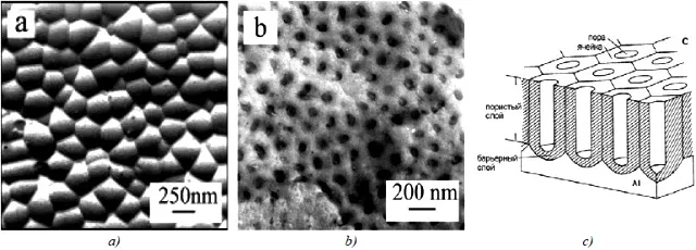
Figure 8 — An example of an industrial anodized aluminum surface: a - porous layer replica, b - barrier layer replica, c - schematic image.
3. Theories of aluminum oxide film formation during anodizing.
There are two theories for the formation and growth of anodic oxide coatings: structural-geometric and colloidal-electrochemical.
3.1 Structural-geometric theory (Keller cells).
From the standpoint of this theory, when an anode voltage is applied to an aluminum electrode (i.e., it is connected to the "plus"), a compact oxide film is first formed (a barrier layer 1-1.1 nm thick /B), which has a hexagonal cellular structure, and the growing coating will repeat it.
The outer part of the cells in aggressive oxide-dissolving electrolytes begins to break down in defective places and turn into a porous coating. The destruction of the barrier layer, leading to the formation of a pore, proceeds, according to some researchers, in the center of the cell, according to others – at the junction of cells.
Thus, under the influence of local impacts of electrolyte ions, pores appear in the barrier layer, the number of which is inversely proportional to the voltage. The pore diameter and their number depend on the nature of the electrolyte and the process mode. In the pore, the barrier layer thickness decreases and, as a result, the electric field strength increases, while the ion current density increases along with the oxidation rate. But, since the temperature in the pore channel also increases, which contributes to the etching of the pore, dynamic equilibrium sets in, and the thickness of the barrier layer remains practically unchanged. The cell size increases with the growth of the forming voltage. An example of a Keller cell is shown in Figure 9. The shape of the pore differs for different authors - from round to "star".

Figure 9 — Keller cell.
The growth of the anodic oxide layer occurs at the bottom of the formed pores due to the transformation of ever deeper metal layers into oxide. Subsequently, under the action of the electrolyte, the oxide that forms the walls of the cells is hydrated. In this case, water, electrolyte anions and anodic reaction products are adsorbed.
3.2 Colloid-electrochemical theory of Bogoyavlensky.
The presence of electrolyte anions in the composition of the oxide layer made scientists associate growth and structural features with the colloidal structure.
From the standpoint of Bogoyavlensky's theory (Figure 10), the formation of anodic oxide films begins with the appearance of monons - the smallest oxide particles with adsorbed electrolyte anions. Monons are generated as a result of the meeting of ion flows. Monones are the nuclei of future micelles.
As the number of monons increases, they turn into polyions - fibrous rod-shaped micelles of a colloidal degree of dispersion, which form the skeleton of an oriented aluminum oxide gel. Electrolyte anions are introduced into it, partially losing their hydration shell.
The adsorption of anions and water, carried out through intermicellar pores, causes a negative charge of monones and micelles, forcing them to adhere tightly to the anode and coalesce with the metal, preventing micelles from merging into a pore-free layer. The pores in this consideration represent a natural intermicellar space.
Along with the formation of micellar layers with the participation of anions, coupled processes of dissolution of the formed oxide proceed.

Figure 10 — Illustration of Bogoyavlensky's theory.
It is interesting to note that the size of the Keller cells is close to the size of Al(OH)3 gel micelles. Interpretation of the anode film growth mechanism from the standpoint of colloidal chemistry makes it possible to explain the introduction of electrolyte anions and cations and individual components of the oxidized alloy into its structure. In this case, the conjugation of the processes of oxide formation and its dissolution in the electrolyte is also taken into account by the colloidal theory.
3.3 Modern coverage structure research.
Now it should be noted that the structure of anodized aluminum can actually be quite far from the ideal described in theory. In particular, the theory speaks of regular hexagonal cells, in the center of which there is one pore. In fact, such a structure can only be obtained by special methods, for example, by multi-stage anodizing in certain modes. Examples of such "correct" coatings are shown in Figure 11. A deeper description of the nanostructured anodic oxide will be given below.
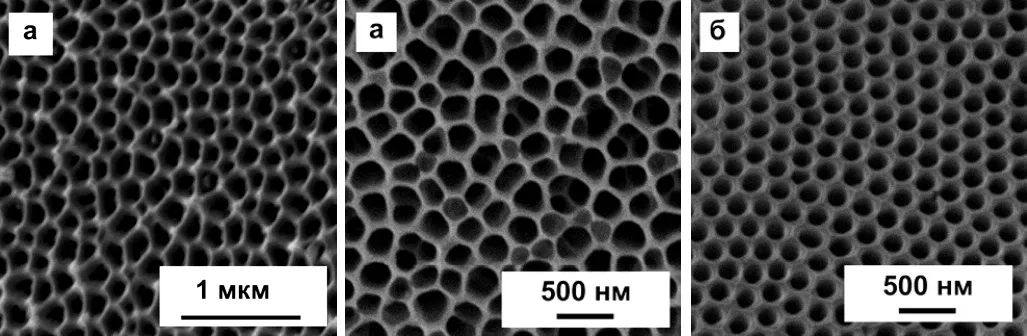
Figure 11 — Examples of ideal and near-ideal cells of the porous layer in the anodic coating on aluminum.
More often you can see more "dirty" options. Examples of them were shown at the beginning of the article.
Besides, the theories do not suggest the possibility of pore branching, which is observed in reality.
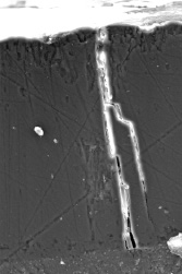
Figure 12 — Pore branching example
4. Features of the growth of aluminum oxide during anodizing.
The formation of the oxide layer occurs at the bottom of the pores, where only a thin barrier layer, whose thickness practically does not change during processing, serves as an obstacle to the passage of electric current. From this point of view, it is possible to increase the thickness of the oxide layer without a significant increase in the voltage on the bath. The resulting pores have the shape of a cone, expanding towards the outer side of the coating, since this part is longer exposed to the aggressive effects of the electrolyte.
It should be noted that the formation of a porous structure is a necessary condition for the growth of an oxide layer. Aluminum oxide is a poor conductor of electricity, and the pores, although filled with electrolyte, have a very small diameter, so the anode resistance is many times higher than the cathode resistance and electrolyte resistance. The change in the potentials of the electrodes themselves due to polarization is insignificant compared to the applied voltage, so the change in voltage over time at a constant current density is determined by the change in the ohmic resistance of the anode.
If the process is carried out at a constant current density, i.e. at a constant rate of oxide formation, the growth of the film will be retarded by the increasing resistance of the electrolyte in the pores. Further growth requires either an increase in the applied voltage or etching of the pores. In practice, the second factor prevails. This is facilitated by a significant release of heat in the process of anodic oxidation, and the main part of the heat is released in the barrier layer at the bottom of the pores. It is believed that during anodic oxidation in 15% sulfuric acid at 21°C and a current density of 1.29 A/dm2, the conditions created at the base of the pores correspond to a 53% solution of sulfuric acid at a temperature close to boiling (about 128 ° C). In this case, the anode temperature rises by 10-20°; depending on the process conditions. Therefore, the growth of an oxide film at a constant current density is accompanied by a continuous increase in the rate of oxide dissolution. The limiting film thickness is reached when the rate of its formation under the action of an electric current becomes equal to the rate of chemical dissolution by the electrolyte. Excessive overheating of the electrolyte at the base of the pores and a local increase in its aggressiveness can lead to etching of the oxide layer and the formation of poor-quality coatings with increased porosity and poor adhesion to the metal.
when the rate of its formation under the action of an electric current becomes equal to the rate of chemical dissolution by the electrolyte. Excessive overheating of the electrolyte at the base of the pores and a local increase in its aggressiveness can lead to etching of the oxide layer and the formation of poor-quality coatings with increased porosity and poor adhesion to the metal.
when the rate of its formation under the action of an electric current becomes equal to the rate of chemical dissolution by the electrolyte. Excessive overheating of the electrolyte at the base of the pores and a local increase in its aggressiveness can lead to etching of the oxide layer and the formation of poor-quality coatings with increased porosity and poor adhesion to the metal.
The rate of dissolution of the oxide film in sulfuric acid increases with increasing temperature, while the activation energy of the dissolution of the anode film is estimated at 17 kcal/mol, which indicates that the rate is controlled by the kinetic stages of the chemical dissolution process. The rate of chemical dissolution of aluminum oxide is relatively high, especially in aggressive solutions of sulfuric acid.
Increased dissolution of the oxide stimulates an increase in the concentration of aggressive acid, temperature and duration of the process:
- at 20°C in a 20% solution of sulfuric acid for commercially pure aluminum, D16 and AL9 alloys, the dissolution rate is 0.2, 0.14 and 0.18 g/dm2·h.
- When the electrolyte temperature doubles, the dissolution rate increases by 6 - 7 times.
- When the concentration of sulfuric acid is increased from 180 to 350 g/l, the dissolution rate increases by about 15%.
Oxide dissolution is expressed not only in the etching of the surface layer of the emerging coating, but also in an increase in its porosity. The presence of copper and magnesium in aluminum alloys also slightly increases the rate of oxide dissolution in sulfuric acid.
Thus, the ratio of the rates of oxide formation and its chemical dissolution predetermines both the thickness and structure of the resulting anodic oxide coatings on aluminum.
Due to the fact that the resulting oxide layer has a high resistance, the electric current during the oxidation process is automatically redistributed to those areas where the resistance is less. Thus, conditions are created for obtaining an oxide layer uniform in thickness on parts of a complex configuration. Therefore, the scattering power of electrolytes for anodic oxidation of aluminum and its alloys is very high. However, it should be taken into account that with insufficient heat removal from the coating being formed, the possibility of local etching of individual sections of the coating arises, which will not be compensated by an increase in the current density in these sections. This will lead to local defects in the coating, up to its complete absence.
Due to the partial dissolution of the base metal during anodic oxidation, the current output is always less than 100%. It decreases with increasing temperature and duration of electrolysis. For example, when alloy D16 is oxidized in sulfuric acid at a temperature of 7°C, the current efficiency is practically independent of time and is 85%, but if the process is carried out at 20°C, then the current efficiency drops from 50-60% during the first 20 min to 15-30% with oxidation for 90 min. The consumption of electricity for gas evolution is small and at moderate current densities (up to 1-2 A / dm2) does not exceed a few percent, but can increase with an increase in current density and the amount of alloying elements in the alloy being processed.
5. Properties of oxide coatings on anodized aluminium.
5.1 Corrosion resistance and porosity.
The anode coating on the surface of aluminum and its alloys is beneficial to its corrosion resistance in many environments where the oxide is more resistant than the base metal. It successfully protects aluminum from atmospheric corrosion, in neutral and slightly acid solutions of inorganic salts:
- The resistance of anodic oxide coatings in the sea atmosphere and sea water is confirmed by many years of operation of oxidized aluminum parts.
- Anodic oxidation reduces corrosion of aluminum in acetylene, sulfur dioxide, boric acid and benzenesulfonic acid, ethanol and ethanol solutions.
- in the presence of moisture, the coating hydrates along the pore walls with the formation of boehmite or hydrargilite, which contributes to an increase in the weight of the coating, its compaction and a decrease in the corrosion rate over time.
- in chloride-containing media, the corrosion process has a pronounced local character, flowing through the pores of the coating; it is accompanied by the formation of aluminum hydroxochlorides of variable composition, gradually turning into hydroxide, which also contributes to the gradual clogging of pores and slowing down corrosion.
Figure 13 shows corrosion curves for bare aluminum and aluminum with anodic coatings.

Figure 13 — Corrosion curves for bare and anodized aluminium: SAA - water sealed coating, IC - inorganic dye filled coating, BD - organic dye filled coating, EC - electrochemical painting, Bare Al - bare aluminium. Corrosive medium - 3.5% sodium chloride solution.
For pure aluminum, the corrosion resistance is 0.5953 kΩ, the corrosion current is 130.86 mA. After anodizing, the corrosion resistance increases to 24.216 kΩ, and the corrosion current drops to 7.494 mA.
According to the corrosion curves, you can see that the corrosion potential shifts to the negative area in the series SSA, IC, BD, EC, pure Al. In the same row, the corrosion resistance of aluminum also decreases.
The atmospheric corrosion rate of pure aluminum is 0.4284 mm/yr. After anodizing, the corrosion rate is reduced to 0.0817 mm/year.
Microimages of anodized aluminum surface with various types of sealing and filling before and after corrosion are shown in Figure 14.

Figure 14 — Microimages in topographic contrast mode of anodic oxide coatings: SAA - metal anodizing with sealing in water; BD - filled with black organic dye; IC - filled with inorganic dye; EC - with electrochemical staining in tin salts.
Based on practice, the minimum thickness of oxide coatings that protect products is selected according to operating conditions:
- indoors with artificially controlled climatic conditions - 9 microns;
- outdoors in rural, forest, mountainous areas away from industrial facilities - 15 microns;
- outdoors in urban and seaside atmosphere - 21 microns;
- in the open air in the industrial atmosphere of the northern coast (chlorides not less than 10 mg / m2 * day) with prolonged moisture - 24 microns;
- when applying varnishes and paints, it is allowed to reduce the coating thickness to 9 microns when used outdoors and to 15 microns in the marine atmosphere.
The best corrosion resistance is noted for coatings obtained on pure aluminum.
The addition of copper, silicon, iron, magnesium, manganese to aluminum improves the mechanical properties of the alloy, but worsens the protective ability of the resulting oxide coatings. Silicon and Al6Mg intermetallic compound oxidize much more slowly than aluminum and remain as inclusions in the coating. In contrast, the intermetallic compounds Al3Mg2, Al2Cu, CuAl2, CrAl7 sub>, Co2Al9, Co2Al5,Co4 Al13, Al7CuFe, Al6CuNi are easily destroyed and increase the porosity of the coating. So, the corrosion resistance of coatings with a thickness of 2.5-10 microns, obtained on the AD1 alloy is 6-7 times higher than the coatings on the 1915 and AD31 alloys, and 2-3 times higher than the coatings on the AMg2AP alloy. Increasing the thickness of the coatings to 15 µm smooths out these differences.
The corrosion resistance of oxide coatings increases with the thickness of the barrier layer, which accounts for approximately 1/3 of the corrosion resistance provided. At the same time, an increase in the thickness of the porous part of the coating has a beneficial effect on their corrosion resistance only in the case of relatively thin coatings, while a further increase in thickness is accompanied by an increase in the pore diameter and a decrease in protective properties.
|
Electrolyte |
Operating temperature |
Bath voltage |
Number of pores per 1 m2 n*1012, pcs |
|
Sulfuric acid (15%) |
10 |
15 20 30 |
79,1 53,1 28,4 |
|
Chromic acid (3%) |
29 |
20 40 60 |
22,2 8,28 4,29 |
The porosity of the oxide surface layer varies from 15 to 40% depending on the grade of the alloy and the anodizing mode. With an increase in the temperature of the electrolyte, the porosity increases.
The corrosion resistance of films slightly increases with their thickness, however, the increase in its porosity and the formation of cracks in the surface layer accompanying the build-up of the coating sharply increases the rate of corrosion damage.
The protective ability of anodic oxide coatings can be significantly improved by filling the pores in various solutions containing anti-corrosion agents. A promising way to improve the corrosion resistance of anodic oxide coatings is the creation of combined coatings, in which the porous oxide plays the role of an adsorption layer that retains an organic polymer material that is resistant to aggressive environments.
5.2 Physical, mechanical and electrophysical properties of aluminum oxide.
Protective and decorative oxide coatings obtained in aqueous solutions of sulfuric acid have high electrical characteristics. The microhardness of oxides obtained at a current density of 0.5-2 A/dm2 is H 300 - 500, while commercially pure aluminum is about H 30. The microhardness of anode films measured on a PMT-3 microhardness tester , on technical aluminum it can reach H 600, and on chemically pure aluminum - H 1500. At the same time, the microhardness of the resulting coatings is uneven in thickness: the layers adjacent to the metal have a microhardness 50-100% higher than the outer ones, which is associated with a greater porosity of the surface layers .
The microhardness of functional anodic oxide coatings depends on the nature of the aluminum alloy and is (GPa):
- on pure aluminum - 4.9-5.1,
- on alloy AB - 4.7-4.9,
- on AL type alloys - 4.4-4.7,
- on alloy D16 - 3.24-3.53.
The highest quality coatings are formed on pure aluminum and its alloys with magnesium, the lowest quality coatings are formed on alloys with a copper content of over 4.5% (D1, D16, D20)
Anodic oxide is a good dielectric: resistivity is on average 4•1015 ohm•cm, breakdown voltage can reach 1 kV or more.
To improve the strength and electrical insulating properties, thicker coatings are obtained (usually 40 - 90 microns, although oxidation to a thickness of several tenths of a millimeter is possible). In some industries (instrument making, mechanical engineering, aviation technology), the thickness of coatings is limited to 75 microns due to the high probability of cracking on thick coatings and defective coatings on parts with sharp edges, which drastically reduces the electrical insulating ability and wear resistance of the coating.
The electrophysical properties are affected not only by the thickness and porosity, but also by the structure of the coating, so the results are highly dependent on the composition of the electrolyte and the processing mode.
Thus, coatings obtained in a sulfate solution with modifying additives on AD0 aluminum with a thickness of 84 microns and a porosity of 14% had a breakdown voltage of 2.5 kV, while coatings with a thickness of 165 microns with that the same porosity - only 1.5 kV.
161 µm thick films at 9% porosity showed a breakdown voltage of 1.83 kV, and 154 µm thick coatings at 23% porosity showed 2.33 kV.
The breakdown voltage on cast alloys is lower than on wrought alloys.
The thermal insulation properties of oxidized aluminum alloys are higher compared to non-oxidized metal. The thermal conductivity of aluminum oxide is 0.004-0.012 J/(cm·s·°C), which is 200-500 times lower than that of pure aluminum. The thermal radiation coefficient of an anodized surface is 10 times higher than that of pure metal.
Thick films on aluminum alloys are highly resistant to high temperatures, withstanding temperatures up to 2000°C. Therefore, oxidation is used in the manufacture of molds for casting aluminum and magnesium alloys. With prolonged repeated exposure to high temperatures, microcracks form on the oxidized surface due to the difference in the values of the coefficient of linear expansion of the anode film and aluminum.
The growth of the oxide layer is associated with partial dissolution of the base metal and the surface layer of the resulting oxide, which affects the size of the part during processing. In the first half hour of treatment, the size of the oxidized part increases by 1–2 μm, but then the size decreases to -2 μm after 1 hour of treatment and beyond. Therefore, when applying thick coatings, it is necessary to take into account the change in the size of parts during the coating process. The increase in the size of the part during the anodic oxidation of aluminum and its alloys is less than the thickness of the resulting coating. Typically, the increase in part size is from 30 to 60% of the obtained thickness of the oxide layer in various electrolytes (on average 50%).
6. Sealing and coloring of anodic oxide films on aluminium.
Significant porosity of the oxide coating leads to the fact that it easily adsorbs moisture, various solutions and organic substances. Porosity during anodic oxidation plays a positive role as a necessary factor for increasing the thickness of the oxide layer, however, during operation, unclosed pores are the weak point of the coating, through which the corrosion process will primarily occur. Therefore, after the formation of a porous oxide, it must be subjected to additional processing designed to close the pores - either with hydrated alumina (when compacted with water, in inorganic and organic substances), or with various varnishes, oils and other substances with appropriate impregnation.
The ability to adsorb organic substances underlies the coloring process of anodic oxide coatings (Figure 15, 16).
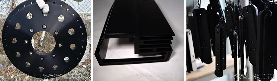
Figure 15 — Examples of anodized aluminum parts filled with black dye.
Transparent and translucent protective and decorative coatings of aluminum and its alloys are painted with aqueous acidic organic dyes. The color of the films obtained in different anodizing electrolytes differs due to the difference in the structure, porosity, and natural color of the coatings. To obtain the desired colors, mixtures of aniline dyes are used. In addition to organic dyes, inorganic dyes are also used. So, a limited color gamut, but greater light resistance of anodic oxide coatings is obtained by a double exchange reaction in solutions of inorganic salts.

Figure 16 — Examples of anodized aluminum parts filled in turquoise, purple and red dye.
The corrosion resistance of aluminum and its alloys (especially in water and aqueous media) can be greatly improved by sealing in a chromium salt solution. Sodium salt is usually used due to economic feasibility. Compositions for sealing the anodic oxide coating in bichromates are regulated by the DEF151 specification and are based on work originally performed in the USSR and the USA.
There are compositions based on sodium bichromate with sodium carbonate or hydroxide and based on sodium dichromate. Treatment in the first solution for sealing anodized aluminum lasts 5-10 minutes. This time is not enough to carry out the complete compaction of the oxide anode film by hydration, but it ensures the absorption of a significant amount of chromates. The anodic coating then turns yellow. The intensity of yellow staining increases depending on the thickness of the coating.
The second composition for densifying anodized aluminum in bichromate without other additives implies processing over the time that was spent on the anodizing itself. This composition provides a satisfactory degree of hydration, but not necessarily a complete seal.
7. Colored anodic coatings.
Coatings can be dyed with more than just fillings in organic and inorganic dyes. They can also be colored directly from certain electrolytes.
If in these electrolytes aluminum and its alloys are anodized first with alternating current and then with direct current, then the coatings are colored from light straw to golden and bronze.
Another way to color anodized aluminum is electrochemical treatment in tin or nickel salts.

Figure 17 — Examples of anodized aluminum parts
8. Anodizing with ordered micropore architecture.
8.1 Introduction to ordered anodizing.
The next step in the evolution of the anodizing process is anodizing with an ordered micropore architecture. In fact, this is already nanotechnology, because. in the process, nanopores of perfectly regular shape are obtained (Figure 18d).
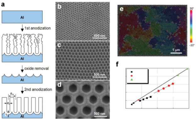
Figure 18 - Schematic of conventional two-step soft anodizing (MA) procedure for self-aligned anodic alumina (AOA) b–d - Representative SEM micrographs of self-aligned AOAs obtained with MA using : b - 0.3 M H2SO4 at 25 V, c - 0.3 M H2C2 >O4 at 40 V and d - 1 wt% H3PO4 at 195 V. e - Color-coded AOA SEM image formed by two-stage SA using 0.3 M H2SO4 at 25 V, demonstrating the polydomain structure. An area with the same color is composed of a domain. pores,
Such coatings are used today in highly sensitive sensor technology, biomedical, photosensitive devices, information storage devices and energy collection units.
Porous alumina produced by anodizing (AOA) under controlled electrochemical conditions has a significant amount of pores that do not bond to each other. These cylindrical pores extend towards the oxide/metal interface. Each nanopore is covered with a thin hemispherical barrier layer. In general, this is the same hexagonal cell, which in reality rarely has such a correct appearance in traditional aluminum anodizing.
The cells are further self-organized into honeycombs (hexagonal close-packed structure). Self-ordered nanoporous anodic oxide coatings can be obtained with a uniform pore diameter of 20-400 nm and a density of 108-1010 pores/cm2.
Initially, it was believed that only soft coatings are suitable for nanoporous architectural anodizing - in the hard anodizing mode, microcracked, heterogeneous films are formed.
8.2 Obtaining nanoporous AOA in the soft anodizing variant.
The first information about the possibility of ordered anodization was obtained in 1995. When anodizing aluminum in a special electrolyte for 160 hours under potentiostatic conditions, Masuda and Fukuda found that the films exhibited an autonomous cell configuration at the bottom of the coating.
There was a rearrangement of the initially disordered layer, and the size of the idealized zone increased with the time of anodization, but did not exceed a few micrometers.
Further development of the process led to a two-stage anodization (picture)
Experimental observations led to the development of the “two-stage anodizing” process, which can be used to obtain nanoporous AOA with a highly ordered arrangement of uniform nanopores (Figure 18 a).
Many studies have shown that AOA structural parameters:
- Dp - диаметр пор.
- Dint - interpore distance.
- tb - thickness of the barrier layer.
formed in self-ordering modes depend primarily on the voltage at the bath U (more precisely – anode potential).
Ordered AOAs are applied in a limited technology window known as "self-align mode". It has a self-organized growth of ordered nanopores (Figure 18 (b–d)):
- sulfuric acid (H2SO4) at 25 V for hole spacing Dint</sub >= 63 nm
- oxalic acid (H2C2O4) at 40V for D< sub>int = 100 nm
- phosphoric acid (H3PO4) at 195V for Dint= 500 nm.
Dint and tb depend linearly on U with proportionality constants ζ = 2.5 nm*B–1 for Dint and .eta; = 1.2 nm*B–1 for tb (Figure 18 f). The potential dependence Dp is not as sensitive as the interaction between current density and temperature, concentration and nature of the electrolyte used.
Nielschetal found empirically that self-ordering of AOA requires a porosity of P=10%, regardless of U, electrolyte composition, and anodizing conditions. P is calculated as the ratio of the surface area of the pores to the area of coverage. P = (π/2*31/2) (Dp/Dint) 2 * 100.
It is believed that stationary growing nanoporous films are formed while maintaining a dynamic balance between the rate of field oxide dissolution at the electrolyte/oxide interface and the rate of oxide formation at the metal/oxide interface. This mode maintains a constant barrier layer thickness.
Obtaining AOA with nanopores is possible in the self-organization mode. The structure of such an oxide obtained in a two-stage process has a polydomain structure. This means the presence of ideal domains separated by the boundary of defective pores. A single-domain AOA configuration over an area of several mm2 was first demonstrated by Masudaetal. In this case, anodizing aluminum with a pre-applied pattern was used. In this process, the primary (before anodizing) texturing of the surface by nanoindentation with a stamp takes place (see Figure 19).
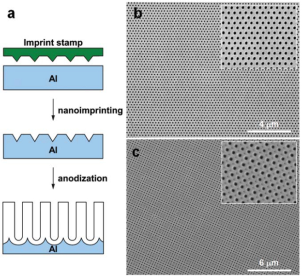
Figure 19 - Scheme for manufacturing a perfectly ordered AOA using a stamp.
and – process steps; b,c - typical SEM micrographs of a long-range ordered AOA with: (b) - hexagonal and (c) - square arrangement of nanopores.
Each stamp imprint initiates the nucleation of pores and leads to their orderly localization. In addition to round holes, the method allows other shapes to be obtained: square and triangular, in a densely packed square or hexagonal arrangement. Instead of a stamp, some scientists have been able to use focused ion beam (FIB), holographic lithography, and microsphere lithography. The possibility of arbitrarily changing the interpore distance Dint.
Pre-stamping helped produce single-domain coverages, but there was an important limitation. The realizable maximum aspect ratio or depth of nanochannels maintaining the initial hole configuration depended critically on the anodizing conditions. A high aspect ratio of homogeneous nanopores can only be obtained in a narrow processing window (self-ordering mode), which practically limits the range of choice in interpore distance: Dint = 63 nm for anodizing in H2SO4 at 25 W, 100 um at 40 W in H2CO4 и 500 um at 195 W in H3PO4 respectively.
What are the ways around this restriction? Today, work is underway to adjust acid electrolytes based on H2SO4, H2CO4 and H3
PO4), and the search for new systems. Voltage variations above the process stabilization optimum always lead to "breakdown"; oxide film due to a combination of high current and heat released during its passage.
8.3 Obtaining nanoporous AOA in the hard anodizing variant.
Relatively recently, Lee et al disproved the theory that it is impossible to obtain nano-ordered anode films in the hard anodizing mode. The conventional hard anodizing process itself was developed in the early 1960s and was characterized by a high speed of 50 - 100 µm/h. Its use in nanotech anodizing has been limited. However, this process has not been used in current nanotech research due to difficulties in controlling important structural parameters such as Dp, Dint and nanopore aspect ratio. The solution was found by Leeetal by pre-anodizing before hard anodising. In addition to this, precise temperature control was required. As a result, it was possible to suppress the “burning” and grow self-ordered AOAs in an oxalic acid electrolyte at U>100 V. A new self-ordering mode was established with a widely adjustable interpore distance Dint = 200-300 nm (Figure 16f). The oxide growth rate was expected to be 25 to 35 times faster than the soft anodizing process. Further, similar data were obtained in other electrolytes. In the oxalic acid electrolyte, the PTA porosity turned out to be 3.3-3.4%, which was one third less than the recommended values for self-ordering of the coating (10%) in the soft anodizing mode.
A new self-ordering regime was established with a widely adjustable interpore distance Dint = 200-300 nm (Figure 16 f). The oxide growth rate was expected to be 25 to 35 times faster than the soft anodizing process. Further, similar data were obtained in other electrolytes. In the oxalic acid electrolyte, the PTA porosity turned out to be 3.3-3.4%, which was one third less than the recommended values for self-ordering of the coating (10%) in the soft anodizing mode.
A new self-ordering regime was established with a widely adjustable interpore distance Dint = 200-300 nm (Figure 16 f). The oxide growth rate was expected to be 25 to 35 times faster than the soft anodizing process. Further, similar data were obtained in other electrolytes. In the oxalic acid electrolyte, the PTA porosity turned out to be 3.3-3.4%, which was one third less than the recommended values for self-ordering of the coating (10%) in the soft anodizing mode.
Leeetal went further and realized the production of membranes with periodically modulated nanopore diameter along the pore axes by a combination of soft and hard anodization with appropriate solution replacement (Figure 18 a). More recently, they additionally showed that AOAs experiencing spontaneous current oscillations with an amplitude of 0.8 A/cm2 in the potentiostatic regime can have modulated pore structures in which the modulation contrast is proportional to the amplitude of the current oscillations. They allowed deliberate manipulation of the current during the anodizing of the aluminum (Figure 20b).
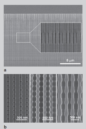
Figure 20 - SEM microimage:
a is a cross-section of AOA obtained by a combination of soft anodizing and hard anodizing; b– cross section of AOA that experienced spontaneous current fluctuations during hard anodization. The oscillating current profiles determine the geometry of the internal pores of the nanoporous AOA.
Fabricated AOAs with modulated pore structure can be source materials for developing 3D porous architectures for:
- Photosensitive devices,
- Model systems for studying particle separation and adsorption characteristics of molecules.
- Template materials in the fabrication of nanowires or nanotubes whose diameters are periodically modulated along their axes and thus allow the study of various physical properties due to surface topography.
8.4 Pulse anodizing.
The combination of soft (low potential) and hard (high potential) anodizing modes allows a unique process of continuous structural engineering of nanoporous AOA based on pulsed anodizing of aluminum under potentiostatic conditions using H2SO4 or H2C2O4 (Figure 21 a). ;
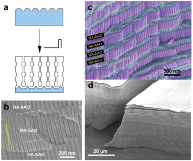
Figure 21 – a - Scheme of manufacturing AAO with modulated pore diameter by pulsed anodizing; b,c - SEM images showing a cross-sectional view of freshly prepared AOA formed by pulsed anodization of H2SO4; d - SEM image of a stack of nanoporous AOA membranes. All plates of MA-AOA segments were peeled from pre-prepared AOA by selectively removing TA-AOA segments using H3PO4.
During the process, the current density periodically changes to a value corresponding to each impulse potential: iMA for UMA and iTA for UTA, iMA<iTA). Thus, the pore structure of the obtained AOA is periodically modulated (Figure 21 b).
Nanoporous AOAs formed by the IA process show a layered structure of smaller pore diameter MA-AOA and larger pore diameter TA-AOA, with the thickness of each anodized segment determined by the pulse duration (.tau;MA and .tau;TA) at given anodizing potentials UMA and UTA (figure 21 c).
In pulsed sulfuric acid anodization, the high voltage pulse portion of the coating contains more anionic impurities than the low voltage portion. Accordingly, the pulsed mode leads to periodic modulation of the coating composition along the pore axes. Segments with a higher impurity content are less corrosion resistant, for example in 5% H3PO4. Therefore, the further use of such an etchant makes it possible to completely delaminate the stack into individual membranes (Figure 21 d), forming an economical and continuous method for their production.
An important advantage of pulsed nanostructured anodizing is the fact that mode alternation contributes to better heat dissipation from the surface of the workpieces. Aluminum anodizing is exothermic, and the chemical dissolution of the oxide with an electrolyte – endothermic. The main heating of the anode is associated with the passage of current through the barrier layer. The heat dissipation in this case can be calculated:
Q = Uit = Rbi2t
where:
i – current density.
Rb – barrier layer resistance.
t – reaction time.
Accordingly, hard anodizing generates a lot of heat due to the high current density, about 2-4 orders of magnitude more than soft anodizing. Excessive heat destroys the oxide film and distorts its structure. But, in pulse mode, the accumulated heat during the hard anodizing pulse can be effectively dissipated during the subsequent soft anodizing pulse. Thus, the burn-in of the oxide film is overcome.
8.5 Examples of formation of matrix-film chemosensitive heterostructures using Al through-anodization technology.
The technology of end-to-end self-ordering anodizing is used in the production of sensors, in particular, chemosensitive to certain gases. The sensor is based on a KEF-4.5 (10) silicon wafer, on which a submicron layer of aluminum is deposited by sputtering, which is then anodized and coated with oxides of titanium, tin, tungsten, molybdenum or zinc.
For two-stage end-to-end anodizing, 0.3-0.5M malonic acid solution in potentiostatic mode can be used. As a result, it is possible to obtain a cellular-porous structure with a pore diameter of 100-200 nm and an average cell size .minus; 500 nm, which favors the conformal deposition of functional chemosensitive coatings. When using oxalic acid, the pores are smaller in diameter, tartaric – more (Figure 22)
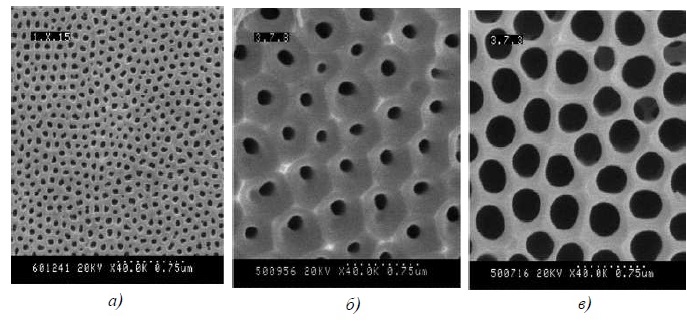
Figure 22 – Microscopic images of the surface of anodic alumina films formed in solutions of (a) oxalic, (b) malonic, or (c) tartaric acid.
Chemical and electrochemical technologies are used to deposit a functional oxide film on an anodized matrix: methods of deposition from film-forming solutions or sols, molecular and ionic layering, electrodeposition, electrophoretic deposition from sols, ultrasonic deposition.
For example, to form a layer of SnxZnyOz, electrochemical oxidation
Sn2+→Sn4+
in 1% SnSO4 solution on the surface of the porous structure of an anodized film with tin (IV) hydroxide deposition in the pores. Then comes the dehydration annealing. At the second stage, zinc hydroxide is chemically deposited on the surface of the formed tin (IV) oxide by treatment in a 0.01 M solution of ZnSO4 and 1% KOH solution. Finally, annealing is carried out at 750°; C within 30 min.
By applying TiO2 onto a porous matrix by electrophoretic deposition, island-type films with a block structure can be obtained. The same films obtained by the layering method are characterized by an increased uniformity of the profiled surface modification compared to the treatment in film-forming solutions with ultrasound.
The ion layering method makes it possible to obtain films that most evenly fill the oxide anode matrix. The layer is characterized by a continuous structure Si/Al2O3/SnxMoyOz и Si/Al2O3/SnxWyOz (Figure 23).
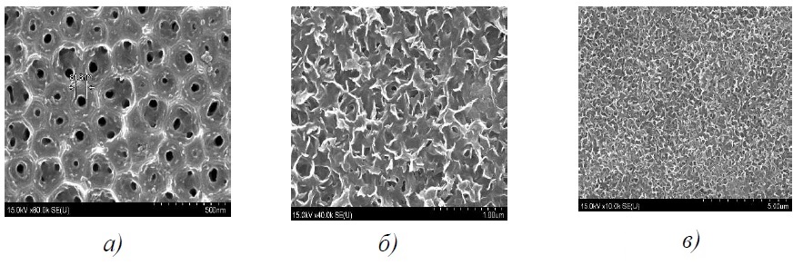
Figure 23 – Microscopic images of the surface of structures n-Si/Al2O3/TiO2 (а), n-Si/Al2O3/SnxMoyOz (б) и n-Si/Al2O3/SnxWyOz (c) generated by the method chemical deposition (a) or ion layering (b, c)
8.6 Preparation of copper nanowires using nanostructured anodized aluminum matrices.
A new stage in the development of modern applied electrochemistry has become the production of nanoscale objects, for example:
- metal and semiconductor nanocomposites.
- copper oxide films.
- microwires, incl. multilayer nickel with high magnetoresistance, used as infrared polarizers.
- Superlattices on which various quantum optical, electronic and optoelectronic effects are observed.
- superconducting nanowires.
These materials are also obtained for studying magnetic fields in layered structures, measuring resistance at low temperatures, and studying magnetoresistance.
Copper nanowires are obtained using various methods:
- Lithographic. Kanaks are prepared in the SiO2 layer, into which copper is deposited.
- Thermal deposition of copper tracks.
- Electrodeposition in polymer and nanostructured anodized aluminum (AOA) membranes.
Polymer membranes are made by bombarding the starting material with nuclear fission fragments. In this case, tracks from 6 to 20 nm are formed. Then they are etched until pores are formed.
Porous AOA membranes are prepared by anodizing aluminum metal in an acidic solution as described above. The membranes should contain a hexagonal network of strictly vertical cylindrical pores (in contrast to the inclined ones in polymer membranes). After anodizing, there is no pure aluminum left in the membrane, so the current lead is created by sputtering metal on one side of the membrane.
A typical current transient for potentiostatic metal electrodeposition into a matrix is shown in Figure 24.
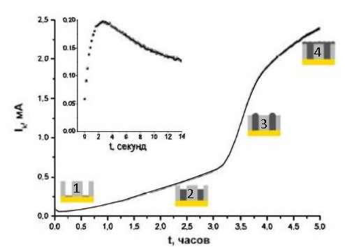
Figure 24 - Current versus time for potentiostatic deposition of Cu into the AOA matrix.
The curve contains 4 sections:
- The first corresponds to nucleation - the “current-time” has a maximum. To describe the site, the Sharifker and Hills model is used for diffusion control.
- The second one is the growth of wires in the pores. As the metal growth front approaches the outer surface of the membrane, diffusion restrictions decrease and the allowable current density increases. The length of the section is affected by the growth rate of the metal and the depth of the pores.
- Third – the exit of individual wires to the surface, accompanied by an increase in the total area of the cathode. In this case, a sharp jump in current is observed on the curve.
- Fourth – metal overgrowth of the entire membrane. Current growth almost or completely stops
Anodized aluminum matrices can be used not only to obtain pure metals, but also to grow bimetals, such as copper-nickel – a system characterized by similar fcc lattices of components with similar parameters and a combination of nickel ferromagnetism and copper paramagnetism.
To obtain alternating layers of ferromagnet and paramagnet, there are 2 technologies using AOA matrices:
- Single bath – traditional electrodeposition with multiple electrolyte replacement. It is possible to use a rotating cathode, while the minimum thickness of one layer can correspond to 19 angstroms.
- Dual bath – electrodeposition using one bath containing ions of both metals, and the concentration of copper in it is two orders of magnitude lower. The composition of the deposited metal is controlled by changing the potential. The ferromagnetic layer is formed by a nickel-copper alloy.
Sample contamination in single-bath is 15%, dual-bath is 1%.
Next, we can compare the results of obtaining nanowires using polymer and AOA membranes, carried out in the studies of Tsirlina G.A. and Orazbayeva A.N.
Two types of Whatman polymer membranes used in the study were made of polycarbonate, the description of their parameters after clarification by electron microscopy is given in the table below:
| Nominal pore diameter of the membrane, nm | Membrane thickness, μm | pore area, μm2 | Diameter, nm | Pore Density, μm-2 | Weight of deposited copper when pores are completely filled, μg | Calculated charge, C |
| 100 (Mp) | 12,3±0,1 | 0,007±0,002 | 100±20 | 5,35 | 80,4±16,1 | 0,3±0,1 |
| 600 (Bp) | 7,9±0,1 | 0,2±0,05 | 450±20 | 0,35 | 96,6±19,3 | 0,3±0,1 |
Images 25 and 26 are obtained for membranes after thermal vacuum deposition on their opposite side of gold. To avoid deformation of the polymer, the deposition was carried out in layers, no more than 50 nm each.

Figure 25 - SEM image of a polymer membrane with a nominal pore diameter of 600nm.
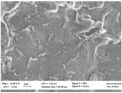
Figure 26 - SEM image of a polymer membrane with a nominal pore diameter of 100nm.
Similarly, the parameters of the AOA membrane are shown in the table below :
| Anodizing voltage, V | The electrolyte used to make the oxide membrane | Dint Distance between pores, nm | Dp Pore diameter, nm | P Porosity, % | Weight of deposited copper at full pore filling (membrane thickness 10 µm), μg | Calculated charge, Kl |
| 120 | 0,3М (COOH)2 | 240 | 120-160 | 23-40 | 400-720 | 1,2-2,1 |
| 40 | 0,3М (COOH)2 | 105 | 40-70 | 13-40 | 230-720 | 0,7-2,1 |
Their microimages are in figures 27, 28.
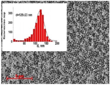
Figure 27 - SEM image of aluminum oxide membrane (anodizing voltage 120V)
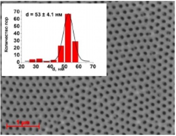
Figure 28 - SEM image aluminum oxide membrane (anodizing voltage 40V)
Gold 250 nm thick was deposited onto the membrane by the magnetron method.
Oxide membranes initially have closed pores, the bottoms are removed by chemical etching. If overetched, they will be uneven, which will lead to the impossibility of high-quality deposition of the current lead.
Copper was deposited in all cases from sulfate electrolyte in a special cell.
The following are the current transients during the deposition of copper nanowires into polymer (BP-600nm) and AOA membranes (Figure 29, 30).
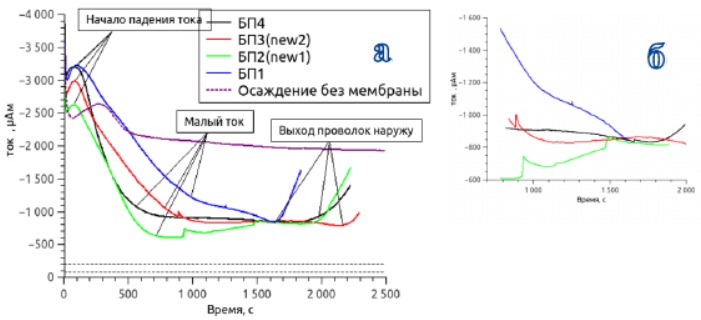
Figure 29 - Current transients when deposited in a polymer membrane with 600nm pores. a - the process of deposition is shown until the moment the wires exit b - deposition at low currents is shown in more detail
High current values in the initial sections of the transient corresponded to the growth of copper under the membranes - due to incomplete gold coverage of the pores, the electrolyte leaked under the membrane.
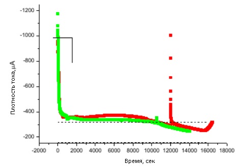
Figure 30 - Current density versus time for potentiostatic copper deposition in an A-15 Al2O3</ matrix p>
Figure 30 shows a sharp decrease in current, which corresponds to the growth of wires in the pores.
The dotted lines in the figures indicate the range of deposition currents into membranes, taking into account the error, assuming that it is proportional to the current during deposition on a smooth substrate without a membrane, taking into account its porosity.</p >
Wire extraction – separate technology. For polymer matrices, this is multiple dissolution in dichloroethane followed by sonication (Figure 31, 32). For AOA matrices - dissolution in 3M NaOH, then in isopropyl alcohol with further sonication (Figure 33).
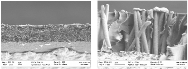
Figure 31 - SEM images of polymer membranes with wires already deposited in cross section
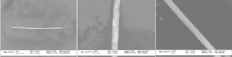
Figure 32 - SEM images polymer wires obtained from polymer membranes
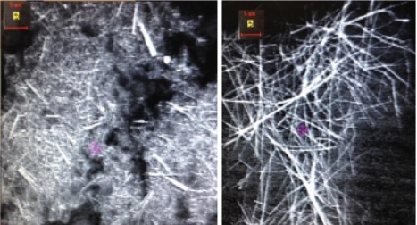
Figure 33 - SEM images of wires obtained from aluminum oxide membranes
If the extraction of the wire from the AOA membranes is not long enough, then it turns out to stick together. It takes up to 4 hours for complete dissolution.
The disadvantages of the methods are:
- Polymer membranes are easier to dissolve, but it is impossible to ensure the continuity of the metal layer on them. Its growth under the membrane does not allow one to control the amount of metal in the wires by the passed charge. Accordingly, the wire suspension is contaminated with sediment fragments under the membrane.
- Oxide membranes require improvement in matrix dissolution technique.

Do you want to become our client?
Just leave your request by filling out the form on the right and we will contact you as soon as possible. Thank you!

By submitting an application, you agree to processing of your personal data. Your data is protected.