


 Fazlutdinov K.K.
 03.12.2016 (updated 25.01.2021)
 61855 views
What is electroplating? Theoretical foundations of applying galvanic coatings.
Content:
1. The concept of electrolysis. Schematic diagram of the electrolyzer.
2. Faraday's law. current output. Calculation of the thickness of the deposited coating.
3. electrode potential. Overvoltage (polarization).
7. Simple and complex electrolytes in electroplating.
8. Chemical deposition of metals.
1. The concept of electrolysis. Schematic diagram of the electrolyzer.
Electroplating — is the deposition of a metal or oxide on the surface of a product to give it new functional properties or improve its appearance. Electroplating is performed under the action of an electric current, hence the concept of "electrolysis".
From a practical point of view, electrolysis is a complex of redox reactions occurring under the influence of an electric current in an electrolyte.
An electrolyte is a medium (for classical electroplating, an aqueous solution) that has ionic electrical conductivity. Simply put, it is a liquid that can conduct electricity through itself. The electric current is conducted mainly by the ions solvated in the solvent. Solvation is a kind of "pulling away" of ions from a solid crystal lattice of a solid by water dipoles. As a result, each ion becomes surrounded by a certain number of water molecules and in this form moves either to the positive or to the negative electrode.
When an electric current is passed through an electrolyte, there is initially a directional movement of electrons in metallic conductors. From the anode, electrons pass to the cathode, as a result of which an excess positive charge is formed on the anode. When the electrical circuit is switched on with an external current source, on the soluble anode, electrons will be taken away from the atoms of the base metal of the anode, and on the insoluble one, electrons will be taken away from those anions that are in the anode region. An excess negative charge appears on the cathode due to the electrons accumulated on it. Oppositely charged anions start moving towards the positive anode, and cations start moving towards the cathode. At the same time, having reached the electrodes, they can undergo certain chemical transformations.
The current passing through the electrolyte is usually constant, although sometimes it can be variable or change according to a certain function. In any case, we can always distinguish cathodic (reduction) and anodic (oxidation) processes.
Electrolysis need not only occur in aqueous solutions. There are also non-aqueous electrochemical systems based on organic (mostly aprotic) solvents, salt melts, and even solid electrolytes, but their industrial use for obtaining metal coatings is limited, and in the case of solid electrolytes, it is completely impossible.
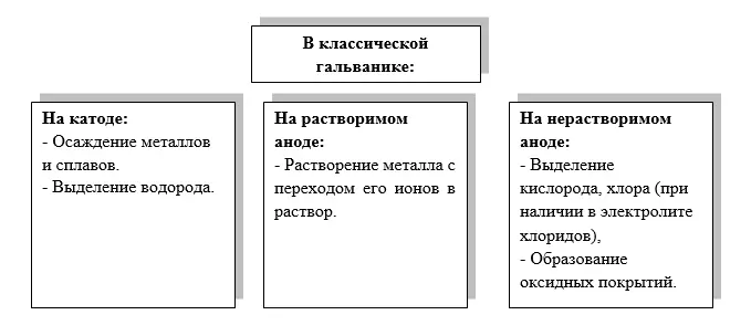
In electroplating, based on the above scheme, there can be three options for organizing the process:
1. Electrolysis with soluble anodes. The anode metal dissolves and its ions go into solution, and the same ions are reduced on the cathode and a metal coating is deposited. Examples of such a process are zinc plating, copper plating, nickel plating, etc.
2. Electrolysis with insoluble anodes. The anode does not dissolve, a side reaction occurs on it, for example, the release of oxygen. At the cathode, metal is reduced, the ions of which are pulled up from the electrolyte. There is a continuous decrease in the concentration of metal ions in the solution.
3. Anodizing — obtaining an oxide coating on a part hung in a bath with an anode, hydrogen is released at the cathode.
The electrolysis device is called an electrolyzer. A small laboratory cell is usually called a cell, while an industrial plant will be called a plating bath.
Scheme of the simplest electrolyzer (Figures 1 and 2) always includes:
- an electrolyte through which an electric current flows;
- cathode(s) - parts to be coated (negative electrical pole, on which the process of accepting electrons - reduction takes place). The cathode on which the coating is applied can also be called the substrate or base, and the coating on the cathode is the deposit;
- anodes - counterelectrodes (positive electric pole, on which the process of electron recoil - oxidation occurs);
- source of electric current.
In the case of anodic oxide coating, for example, on aluminum (anodizing process), the items to be coated are on the anode and the cathodes act as counter electrodes.
The electrolyzer can be equipped with additional equipment:
- heaters;
- mixing systems;
- filtration systems;
- onboard suctions;
- lids;
- sensors of technological parameters (temperature, pH, level, potential, concentration of components, etc.), dispensers and other automation equipment.

Figure 1 - Schematic diagram of an electrolyser

Figure 2 - Real electrolytic cell (galvanizing bath of bright zincating from alkaline zincate electrolyte).
2. Galvanics and Faraday's law. current output. Method for calculating the thickness of the deposited coating.
The primary task in the regular work of an electroplating shop is to obtain coatings of a given thickness and structure on products with the lowest possible economic costs. To calculate the thickness of the coating obtained during electrolysis at a given current, it is necessary to use Faraday's law - the basic quantitative law of electrolysis.
Faraday's law relates the mass of the substance released on the electrode and the amount of electricity passed through the electrolyte. As applied to electroplating, Faraday's law can be represented as follows:
m=A⁄zF*ItBm
where:
m is the mass of the metal released on the cathode, g;
A is the atomic mass of the metal released;
z is the number of electrons involved in the process of metal reduction;
F - Faraday number - 96500 C*mol-1
I - Total current passed through the electrolyte, A;
t - Total electrolysis time;
W - Current output.
Current output — the proportion of electric current spent to complete the target electrochemical reaction. The current efficiency characterizes only the electrochemical process, i.e., for example, with anodic dissolution of copper in a sulfuric acid electrolyte, the current efficiency is close to 100%, however, another 5% can be added due to the chemical dissolution of copper in the electrolyte. As a result, the calculated current efficiency can formally be 105% due to the chemical dissolution of copper.
i=I/S
where:
i - current density, A/dm2;
I - Total current passed through the electrolyte, A ;
S - Electrode area, dm2;
Note that most often the area of parts in electroplating is expressed in square decimeters, and the current density, respectively, in amperes per square decimeter. Less commonly used is the ratio to the square centimeter (scientific experimental work) and the square meter (for example, when galvanizing a steel strip). The use of decimeters in electroplating is convenient because in this case, not too large and not too small values \u200b\u200bare obtained.
Obviously, depending on the electrode in question, the current density can be cathodic and anodic (ik and ia). The deposition rate and, to a large extent, the structure of the coating depend on the density of the cathode current, and the state of the anodes depends on the density of the anodic current (active, in which they dissolve, or passive, when side reactions occur instead of dissolving the metal, mainly oxygen evolution).
It is important to understand that the area of the electrode S can be geometric and real.
The geometric area (and associated geometric current density) is calculated from the geometric dimensions of the part using standard mathematical formulas.
The real area (and the real current density) can be determined from the roughness and microrelief of the surface. So, by comparing the photographs of the silver coating in Figure 3 (A and B), it becomes clear that the surface area of the plate is actually 2-3 times greater than just the length times the width. The real area must be taken into account when electroplating parts with high surface roughness, for example after sandblasting or shot blasting.

A

B
Figure 3 — Microimage of a silver coating on a brass substrate, obtained galvanically from a dimethylhydantoin electrolyte, A - general photograph, B - microimage on an electron microscope in topographic contrast mode with x5000 magnification.
Let's go back to Faraday's Law and replace the current I in the equation with the current density i, and express the mass in terms of the density of the deposited metal:
pV/S=A/zF*I/S*tBm
pV/S=A/zF*itBm
The V/S value is the desired coating thickness δ, if conventionally the coating is taken as a box, then:
The ratio of cathode to anode current output determines the stability of the electrolyte. It is obvious that if during the electrodeposition of a metal with soluble anodes the cathodic current efficiency is greater than the anode one, then the electrolyte will gradually become depleted in the ions of the deposited metal, and if vice versa, it will be enriched. Both will reduce the stability of the electrolyte.
When considering the anode process in electroplating, we will be interested in the mass of the metal dissolved on the anode (this is necessary for a rough estimate of the service life of the anodes). When considering the cathodic process, we will be interested not so much in the mass of the deposited coating (with the exception of precious metals), but in its thickness. Therefore, based on Faraday's law, we can derive the dependence of the coating thickness on the current density.
The current density is an important parameter of the operation of a galvanic installation. It is the ratio of the total current flowing through the electrode to the area of the electrode:
pδ=A/zF*itBm
δ=A/zFp*itBm
Note that coating thickness in electroplating is usually expressed in micrometers (µm).
Calculation of plating thickness in practice is usually made approximately from reference data on the average thickness of the coating deposited from a given electrolyte at a given current density. These data are contained in GOST 9.305-84, or in separate technical processes supplied together with branded organic additives to electrolytes. For example, Table 1 shows the average data for zincate galvanizing from an alkaline zincate electrolyte with two brighteners.
Precise calculation using a formula makes no sense in practice, because it is impossible to accurately determine the real current density and the real current output on each section of a complex profile surface. Therefore, the calculation will always be of an approximate estimated nature. In any case, before choosing the coating deposition mode, the development and measurement of the thickness is carried out on prototypes of parts.
|
Current density, A/dm2 |
0.5 |
1 |
2 |
3 |
4 |
5 |
6 |
7 |
Current output, % |
95 |
92 |
80 |
65 |
55 |
48 |
42 |
40 |
Deposition rate, µm/min |
0.14 |
0.26 |
0.42 |
0.56 |
0.63 |
0.70 |
0.72 |
0.86 |
3. electrode potential. Overvoltage (polarization).
Metal electrodes immersed in an electrolyte solution containing ions of the same name as the metal have a characteristic called equilibrium potential.
In electroplating, the equilibrium potential of an electrode characterizes the dynamic balance between metal ions leaving the crystal lattice of the electrode into the solution and similar ions in solution tending to enter the crystal lattice of the electrode. The exchange rate is characterized by the so-called exchange current i0. Such a system is implemented in any plating electrolyte using soluble metal anodes, for example when we load copper anodes in a copper sulphate electrolyte consisting of copper sulfate and sulfuric acid.
When using insoluble anodes or when lowering the anode into a solution in which there are no ions of the same name, a stationary potential will be realized on it.
The equilibrium potential is tied to the value of standard metal potentials (table values) by the Nernst equation:
E = E0+RT/nF*lnaOx/aRed
where:
E - Equilibrium electrode potential, V;
E0 - standard electrode potential, V;
R - Universal gas constant, 8 ,31 J/(mol*K);
T - absolute temperature, K;
n- number of electrons involved in the process;
F - Faraday's constant equal to 96500 C*mol-1 ;
aOx and aRed are the activities of the oxidized and reduced forms of the substance participating in the half-reactions, respectively.
If we substitute the values of R and F into the equation, go to decimal logarithms and assume that the temperature is 298 K, then the Nernst equation can be convert to the following:
E = E0+0.0592/n*lgaOx/aRed
When we apply a potential difference to the electrodes of the setup (in other words, we connect a constant current source), the potential of the electrode will shift from the equilibrium value. In electroplating, it is generally accepted that the displacement of the cathode potential goes to the negative region, and the anode potential to the positive region, although this is conditional (the inverse ratio of signs can also be accepted).
The displacement of electrode potentials from the equilibrium value under the action of an externally applied voltage is called polarization, the difference between the equilibrium potential and the potential under current is called overvoltage. Polarization and overvoltage are, in fact, synonyms. The degree of dependence of the current density on the potential is called polarizability.
Overvoltage is denoted as ηK and ηA, respectively, to denote the cathodic and anode process.
These issues will be clearly explained when considering polarization curves.
Note that the higher the overvoltage of metal precipitation on the cathode, the finer the coating will be. When depositing coatings, the goal is to obtain as finely crystalline deposits as possible. The rationale for this will be given later.
You should also remember the general rule: predominantly electropositive processes occur at the cathode, electronegative processes occur at the anode.
4. Electrolyzer voltage.
In order for an electric current to pass through an electrolyser, a certain voltage must be applied. With a constant electric current I, the higher the resistance R in the nodes of the cell, the higher the required voltage U. The product U * I is called the power W, measured in kW. The product of power and time (in hours) is called kilowatt-hours and characterizes the cost of electricity for the process. Therefore, ceteris paribus, it is necessary to strive to reduce the voltage on the bath.
The voltage on the working electrolyzer is the sum of the following values:
- Reactions — the voltage required for the passage of target reactions (coating deposition, anode dissolution, etc.). More correctly — this is the sum of the reversible decomposition voltage (the difference between the equilibrium or stationary potentials of the cathode and anode in a given electrolyte), cathodic and anodic polarization ή;
- Utv conductors — voltage required for the passage of electric current through solid conductors: coated parts, anodes, tires, suspensions, wires, etc.
- Ucontacts — voltage drop in all contacts: places of connection of wires to the current source, places of contact of wires with tires, tires with suspension or anode hooks, suspension and coated parts, anode hooks and anodes;
- Uelectrolyte — voltage drop in the electrolyte, determined by the electrical conductivity of the electrolyte;
- Udiaph — voltage drop in anode covers, diaphragms, bells, drums.
The total resistance of a working galvanic bath can thus be expressed by the formula:
Ugen=Ureactions+Usolid conductors+Ucontacts+Uelectrolytes+Udiaph
- As can be seen from the formula, in order to reduce the resistance on a working bath, you need:
- use solid conductors with minimum resistance and sufficient cross section. When current passes through them (with insufficient cross section), they can heat up, which will further increase their resistance.
- Timely clean all the electrical contacts listed above. Use the most corrosion-resistant materials.
- Timely adjust the electrolyte and observe the electrolysis mode. When an electric current passes through an electrolyte, its temperature can rise, which will increase its electrical conductivity, unlike solids.
- if possible, do not use covers and diaphragms (when galvanizing, for example, anode covers will be superfluous, but when nickel plating on pendants, they are indispensable).
5. Limiting stages of the electrode reaction. Polarization curve. Limit diffusion current. Current concentrators.
In order for a metal ion to recover and settle on the cathode, it needs to approach the electrode surface from the solution volume, discharge and integrate into the coating crystal lattice. All these processes are characterized by a certain speed. The step with the lowest rate will slow down the entire reaction. Such a stage will be called the limiting (delayed) stage and will control the electrochemical process.
In electrochemical kinetics the rate of the process can be controlled by slow diffusion (transfer) of discharging ions from the depth of the solution to the cathode surface, their slow discharge (transition of an ion into a metal) or mixed kinetics, when at certain potentials the diffusion of ions will be slow, and at others - their slow discharge. There are also other limiting stages - delayed crystallization and delayed intermediate chemical reaction.
The type of polarization curve will depend on which stage of the process is limiting - the dependence of the current density on the electrode potential.
Figure 4 shows typical polarization curves.
Note that in everyday electroplating, polarization curves in working electrolytes are rarely taken, so we will omit a detailed study of the kinetics of electrochemical reactions, leaving this to the course of theoretical electrochemistry.
Let's consider the cathode space in the electrolyte when the external current is turned on (Figure 5).

Figure 4 — Typical types of polarization curves: A - delayed diffusion, B - delayed discharge, C - mixed kinetics.

Figure 5 — Scheme of the near-electrode space at the moment of switching on the external current (dependence of the concentration of ions C on the distance to the cathode L), where i0<i1<i2<id.
Initially, in the equilibrium state of the system, the concentration of discharging ions in the near-cathode space is high and equal to the concentration in the entire electrolyte volume.. In the absence of an external current, only the exchange current i0 will be observed in the system.</p >
The exchange current characterizes the process of transition of metal ions from the cathode crystal lattice to the solution and back. As soon as the current source of the discharged ions is turned on, the cathode sheath will begin to fall. At the same time, new ions will flow from the depth of the electrolyte due to diffusion at a certain rate.
If the diffusion rate is less than the ion discharge rate, then the concentration of discharged ions in the near-electrode space will continue to decrease with increasing current density. At a certain current density, all ions coming from the depth of the solution will immediately be discharged at the cathode. This current density will be called the limiting current. We will no longer be able to increase the rate of electrodeposition, because new ions simply will not have time to come from the depth of the electrolyte to the cathode surface. It is important to know that for any reaction, the current limit can be reached when the rate of this reaction reaches the limit value. In this case, an area parallel to the potential axis (i.e., the x axis) will be obtained on the polarization curve.
Note that the limiting current area can be diffusive in nature, or, more rarely, kinetic (the terms limiting diffusion current and limiting kinetic current arise accordingly).
Limiting diffusion current ( id) — the current at which the rate of supply of ions of the discharging element (diffusion from the electrolyte volume) is no longer enough to further increase the rate of the electrochemical reaction of the reduction of these ions.
Limiting kinetic current (ik) — the current at which the rate of the process is completely limited by the rate of a slow chemical reaction, which is included in the total electrode process (loss of a complex discharging ligand particle, dimerization of the ion discharge product, etc.), as well as the rate of penetration of the discharged particles through a layer of organic adsorbed on the cathode surface compounds (surfactants: brighteners, leveling additives).
When the electrolyte is stirred, the value of the limiting diffusion current will increase and the value of the limiting kinetic current will not change.
The concept of limiting diffusion current is extremely important in electroplating, because in most cases, when such a current is reached, it is no longer possible to obtain a compact coating - a metal of a powdered (dendritic) structure is deposited. This gives rise to the concept of operating current density or, more commonly, the operating range of current densities.
Range of operating current densities — range of current densities in which it is possible to obtain a high-quality coating of the required structure and with the required properties. For example, when copper plating from sulfuric acid electrolyte without stirring, the operating range is usually 1-2 A/dm2. At a lower current, the coating may become dull, and at a higher current, it may become powdery. The range of operating current densities is especially characteristic during chromium plating.
It is generally accepted that operating current densities in galvanic processes are well below the limiting diffusion current. However, there are examples of coatings deposited at the current limit - for example, coating with a bright tin-bismuth alloy from sulfate electrolyte with a number of organic additives. For example, it is believed that organic additives that help to obtain a compact, shiny, smooth coating begin to act only at currents close to the limiting ones, while at low current densities, the coating turns out to be porous, rough and smearing.
Given the complex geometry of coated parts in electroplating, it is important to understand that the limiting current can be realized not on the entire electrode, but on its individual parts ("current concentrators") - sharp edges, protrusions , as well as in cases where the immersion depth of the part is less than the immersion depth of the anode, etc. (Figure 6.7).

Figure 6 — The distribution of field lines from a longer anode to a shorter cathode, on which there are "current concentrators".

Figure 7 — An example of a nickel-plated part with corners — "current concentrators".
The so-called "burn" — a coating area of dark, gray (up to black) color, having a powdery structure (Figure 8).

Figure 8 — An example of the microstructure of a copper powder coating on a copper substrate.
Also, pH can increase significantly in such areas due to the consumption of H+ ions to release hydrogen gas. In this case, the hydrate formation pH can be achieved for some metals. for example, nickel, and we will also see deposits of metal hydroxides.
If, in parallel with the deposition of metal on the cathode, hydrogen is released (as is the case, again, with nickel plating), then in places where the limiting diffusion current is realized, a significantly greater gas release will be observed than on the rest of the cathode. Given the coarse-grained structure of the coating and its poor adhesion to the base in these places, as well as the significant rate of its growth, the released hydrogen can simply tear off large parts of the coating (the effect of old paint peeling off the painted product) causing the rejection of the entire product. To increase the value of the limiting diffusion current and, accordingly, to expand the operating current densities, as mentioned earlier, electrolytes are mixed.
6. Simultaneous reactions on the electrode. Separation of metal simultaneously with gas. Alloying.
It is rare that only one reaction occurs when an electrode is electroplated. More often, two or more reactions occur simultaneously. The condition for the simultaneous occurrence of two electrochemical processes is the maximum convergence of their discharge potentials. You can classify situations as follows:
- Recovery (precipitation) of the metal simultaneously with the release of hydrogen;
- Restoration (precipitation) of a metal simultaneously with one or more other metals, as well as, sometimes, non-metals and organic substances.
Incomplete metal reduction reactions (Fe3+ → Fe2+), reactions restoration of oxide films, etc.
As a rule, all metal deposition processes in electroplating are accompanied by the simultaneous recovery of impurities from the solution (foreign metals, sulfur, organics, etc.), the reduction products of which are incorporated into the coating and cause a change in its physical and mechanical properties - positive or negative. An example of a positively influencing impurity (you can call it an alloying component) is bismuth in a tin-bismuth alloy, which improves corrosion resistance, prevents the "tin plague" effect, and increases the shelf life of solderability. An example of an alloy with a harmful impurity — Nickel plating contaminated with copper (copper causes a deterioration in the adhesion strength of the coating to the base, deterioration in appearance — loss of luster, formation of a dirty gray coating, deterioration of protective anticorrosion properties).
6.1 Hydrogen evolution simultaneously with metal deposition on the cathode.
Emission of hydrogen simultaneously with coating occurs, for example, in nickel plating, chromium plating, zincate plating, acid tin plating, etc. Hydrogen evolution increases as the limiting diffusion current is approached.
Consider Figure 8, which shows polarization curves for the simultaneous evolution of hydrogen and metal at the cathode. At the potential E1, the share of the total current attributable to the release of the metal is approximately 2/3 of the total current, and the release of hydrogen is 1/3. At a more negative potential E2, on the contrary, the share of the metal deposition current will be 1/3 of the total, and the share of the hydrogen evolution current will be 2/3. And the more negative the potential we set, the greater will be the proportion of the hydrogen evolution current in the total current passed through the electrolyzer.

Figure 8 — Polarization curves for the simultaneous release of metal and hydrogen.
Hydrogen evolution during cathodic metal deposition almost always has a negative effect on the quality of the coating. There are several reasons for this:
- Hydrogen can penetrate the coating and the metal substrate, causing metals to "hydrogen embrittlement".
- Hydrogen can linger on the metal surface, causing the coating to grow around the gas bubble. As a result, a dimple will form, sometimes reaching the — "pitting". This is especially true for nickel plating.

Figure 9 — Scheme of pitting formation due to a hydrogen bubble adhering to the coating
- Hydrogen can create "gas bags" under which coatings will not form (Figure 10).

Figure 10 — Scheme of the formation of gas bags.
On the other hand, very rarely hydrogen can play a positive role, for example, in alkaline galvanizing from a zincate electrolyte. The abundant evolution of hydrogen in this process makes it possible to further clean the surface of the coated parts from contamination and somewhat improve the adhesion strength of the coating to the base in this case (here we will talk about the "cleansing" effect of the electrolyte). However, one should not forget that the abundant release of hydrogen will simultaneously worsen the physical and mechanical properties of the coating due to hydrogen saturation and, accordingly, hydrogen embrittlement. In addition, hydrogen desorbed from the part with a highly stressed coating can cause delaminations in the form of bubbles.
6.2 Simultaneous selection of two or more metals or a metal and a non-metal (alloying).
Fusion can be desirable or undesirable. In the first case, we purposefully want to obtain an alloy with specific properties: tin-bismuth, nickel-phosphorus, etc. In the second - we do not want to get an alloy, but it is formed due to the peculiarities of the technical process or errors in it. So, in alkaline zincate galvanizing with brighteners, up to 1% carbon from organic brightening additives can be included in the coating. Initially, we do not want this, but without the introduction of organics into the electrolyte, we will not get the coating of the required quality. Also, sulfur is incorporated into the nickel coating obtained from a sulfate-chloride electrolyte with organic brighteners. Thus, we are talking about the features of the technical process. However, if the nickel plating electrolyte is contaminated with copper, then incorporating copper into the nickel plating will cause the nickel plating to deteriorate. This phenomenon could have been avoided, because copper got into the solution due to an error in the technical process (for example, copper parts were poorly washed after preparatory operations and the remains of the pickling solution fell into the nickel plating bath).
In order for two electroactive particles to simultaneously recover on the cathode, we need to bring their discharge potentials as close as possible. This can be achieved in the following ways:
- Link one of the particles into a complex;
- Reduce the concentration of one substance compared to another;
- Introduce surfactant.
- Set the appropriate current density. For example, when depositing bronze (copper-tin alloy), depending on the current density, it is possible to obtain a coating with a different tin content - low-tin yellow bronze or high-tin white bronze from the same electrolyte.
7. Simple and complex electrolytes in electroplating.
Traditionally, simple and complex electrolytes are used in electroplating. The difference lies in the form in which the ions of the deposited metal are. Simple electrolytes contain sulfates, nitrates, chlorides, etc. and the deposited metal in them is in the form of a simple salt. Accordingly, electrolytes will be called sulfate, nitrate, chloride, etc. If a mixture of salts is used, then the name will be double, triple, etc., for example, sulfate-nitrate, sulfate-chloride.
In a complex electrolyte, the deposited metal ion is bound into a complex. A characteristic of a complex electrolyte is the instability constant of the complex - the smaller it is, the stronger the complex. In electrolytes, the complex of which has a minimum instability constant, the metal is deposited with the highest overvoltage and, accordingly, the coating is the most finely crystalline, and the scattering ability of the electrolyte and the uniformity of the coating over the thickness are maximum. In practice, the most stable complexes are usually obtained with cyanide ions.
For example, consider Table 4, which shows the instability constants of silver complexes, and Figure 14, which shows some polarization curves of silver deposition from various complexes. Figure 14 shows that the smaller the instability constant of the complex, the greater the polarization, which is visually expressed in a flatter kinetic curve.
In practice, the following types of complex electrolytes are often used: cyanide, ammonia, pyrophosphate, thiocyanate, hydroxide, hydroboron. Other complexes use less often.
|
View of the silver complex |
Vag constant |
Ammonia |
10-3-10-4 |
Bromide |
10-5-10-10 |
Hydroxy |
10-3 |
Iodide |
10-11-10-15 |
Rhodanide |
10-8-10-11 |
Selenocyanate |
10-12-10-13 |
Sulfite |
10-3-10-6 |
Chloride |
10-3-10-7 |
Cyanide |
10-22 |
2,2' dipyridyl |
10-7 |
Thiosulfate |
10-14 |
Ethylenediamine |
10-5-10-8 |
Thioureas |
10-14 |
Trilonate (EDTA) |
10-8 |
Pyrophosphate |
10-7 |
Sulfosalicylate |
No data |
Methanesulfonate |
No data |
Dimethylhydantoin |
10-10 |
 and anode (b) polarization curves")
Figure 14 — Cathode (a) and anodic (b) polarization curves of silver with the same content in the electrolyte: 1 - pyrophosphate, 2 - thiocyanate, 3 - iodide , 4 - synerhosulfosalicylate, 5 - cyanide, 6 ammonium sulfosalicylate.
8. Chemical deposition of metals.
Chemical Metal Deposition (CMP) is a redox reaction. whose product is metal:
Men+ + Red → Me + Ox
The thermodynamic probability of such a reaction is determined by the potential difference between the reducing agent and the oxidizing agent, on the one hand, and the stability of water — on the other hand, since many metals decompose water and cannot be isolated from aqueous solutions.
Hypophosphite ion, formaldehyde, borohydride, hydrazine, variable valence metal ions (Sn2+, Ti3) can be used as a reducing agent + and others). The corresponding equations are given in Table 5. Thermodynamically, the occurrence of any reaction is possible in the region of pH and potentials where the states of the products of this reaction are stable. With regard to HOM, this means that the reaction proceeds in the region where the metal is in the reduced form, and the reducing agent is in the oxidized form. To ensure the flow of the redox process HOM, it is necessary to increase & nbsp; restorative abilities reducing agent (for example, formaldehyde), which is achieved by shifting the pH towards larger values.
|
# |
Balance |
Equilibrium equation |
1 |
H2PO2-+H2 O=H2PO3-+2H++2e |
E=-0.504-0.06pH |
2 |
HCHO+3OH-=HCOO-+2H2O+2e |
E=-0.19-0.09pH |
3 |
BH4-+OH-=BO2</sub >-+6H2O+8e |
E=-0.40-0.06pH |
4 |
N2H4+4OH-=N2</ sub>+4H2O+4e |
E=-0.31-0.06pH |
5 |
HSnO2-+H2O+3OH-</ sup>=Sn(OH)62-+6e |
E=-0.33-0.09pH |
6 |
Ti3+=Ti4++e |
E=-0.04 |
The introduction of a ligand significantly shifts the reduction potential of metal ions (for example, copper) to negative values.

Do you want to become our client?
Just leave your request by filling out the form on the right and we will contact you as soon as possible. Thank you!

By submitting an application, you agree to processing of your personal data. Your data is protected.