


 Fazlutdinov K.K.
 18.11.2021 (обновленно 18.11.2021)
 2038 просмотров
Tinning (Tin plating, tin-bismuth alloy) | Process Mechanism and Technology | Structure and properties of coatings.
Content:
1. What is tinning, tin and bismuth?
2. Tin platin mechanism and coating structure
1. What are tinning, tin and bismuth?
Tinning is the process of applying a thin layer of metallic tin to the surface of a product to give it the necessary characteristics (electrical conductivity, corrosion resistance, solderability, etc.).
Tin is a soft, silvery-white metal. Density 7.28 g/cm3, melting point 232 °C, atomic weight 118.7 g/mol. Under atmospheric conditions, even in the presence of moisture, tin oxidizes slowly. Diluted solutions of mineral acids at room temperature practically do not dissolve tin; it dissolves in concentrated sulfuric and hydrochloric acids when heated. In solutions of caustic alkali, tin is unstable and dissolves when heated to form stannates. With organic acids, tin forms complex compounds, and the potential of tin becomes more negative than the potential of iron, i.e. tin becomes anodic coating.
Corrosion resistance of tin depending on pH is shown in Figure 1. It can be seen that tin is most stable in the pH range from 6 to 9.
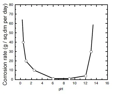 Figure 1 - Dependence of the corrosion rate of tin on the pH value of the medium.
Bismuth is a shiny, silvery-white metal under normal conditions. Density 9.747 g/cm³ melting point 271.35 °C, atomic mass 208.98 g/mol. In compounds, bismuth exhibits oxidation states -3, +1, +2, +3, +4, +5. At room temperature in dry air it does not oxidize, but in humid air it is covered with a thin oxide film. It can form intermetallic compounds with metals - bismuthides.
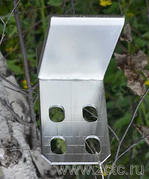
Tin-bismuth coating has found the widest application in electronics and electrical engineering. Most often, current-carrying copper and aluminum busbars, electrical contacts, instrument cases, stainless steel fasteners in contact with aluminum are coated with tin (Figure 2.3).


Figure 2 - Examples of tinned copper busbars.


Figure 3 - Examples of tin-plated body parts.
|
Designation |
Sn - coating with pure tin (tinning); Sn-Bi - tin-bismuth alloy coating; Sn-Bi.gl - tin-bismuth alloy coating with gloss requirements; Sn-Bi (99.7-99.8) 12.gl - coating with a tin-bismuth alloy with a tin content of 99.7-99.8%, the requirement for gloss and a thickness of 12 microns. |
|
Thickness |
3-100 microns (larger thickness is also possible) |
|
Microhardness |
118-198 Mpa (12-20 kgf/mm2) |
|
Specific electrical resistance at 18 °C |
11,5⋅10-8 Ohm⋅m |
|
Permissible operating temperature |
200° C |
|
Permissible content of bismuth in the O-Vi alloy |
0,2-2% |
Pure tin coatings are easy to obtain, but have a number of significant disadvantages: (for more details about some of them, see the article)
• During storage of tin coatings, filamentary crystals grow on their surface, the length of which can reach 5-10 mm (Figure 4). Whiskers cause short circuits when closely spaced electronic equipment is used. The reasons for the appearance of such imperfections in the coating are still not well understood. It was found that the formation of whiskers is largely influenced by the material of the cathode. The main reason is considered to be the presence of internal compressive stresses in the coating, which arise under the influence of the deposition of some impurities, foreign inclusions, diffusion of base components into the coating, stresses in the base material. On tin plated brass, copper and zinc, whiskers appear more frequently and grow faster than on steel. The use of a nickel sublayer inhibits this process.
 Figure 4 - "Mustache" on the tin.
• Tin is a polymorphic metal. Under normal conditions, it exists in the form of the β-modification (white tin), which is stable above 13.2 °C. At low temperatures, white tin transforms into another allotropic modification (gray tin). The transition is accompanied by an increase in the specific volume, which leads to the destruction of the tin coating. This phenomenon is called the "tin plague" (Figure 5).

Figure 5 - Tin rod affected by the "tin plague".
• Pure tin coatings have a very short lifespan as a solder coating. Practice shows that the solderability of a tin coating sometimes deteriorates within 2-3 days. The significant porosity of the coating, the presence of impurities of some metals in the coating, which are included in the process of electrocrystallization or as a result of diffusion of the components of the base metal, for example, zinc from brass, has an adverse effect. The solderability of a tinned surface can also decrease due to the formation of intermetallic compounds such as Cu3Sn, Cu6Sn5 at the copper-tin interface, which lose their plasticity at a thickness of less than 3 microns.
All these disadvantages are eliminated by introducing bismuth into the tin.
The state diagram of the tin-bismuth alloy is shown in Figure 6. However, it is worth noting that galvanic tin-bismuth alloys are alloyed with bismuth by only tenths of a percent - this is already enough to modify the properties of the coating.
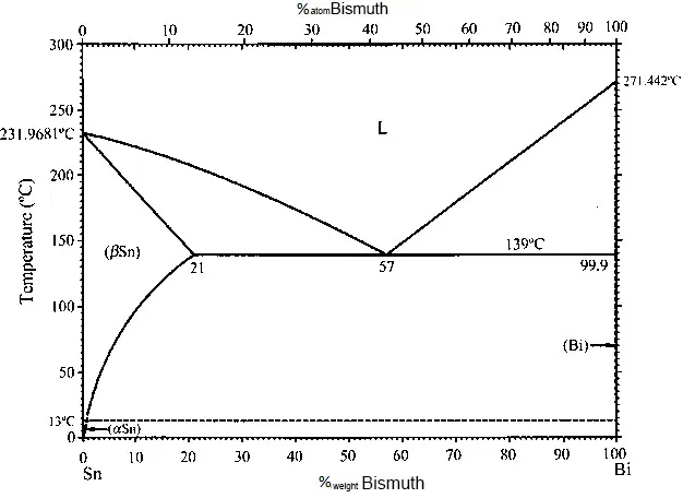
Figure 6 - Tin-bismuth state diagram.
For the deposition of tin and its alloys, electrolytes of different nature are used, the main ones are acidic and alkaline.
2. Tinning mechanism and coating structure.
2.1 Precipitation of individual tin from sulfuric acid electrolyte without surfactants.
The acidic electrolytes of tin plating include sulfate, pyrophosphate, phenolsulfonic, hydrofluoric acid, etc.
The most popular is sulfate, consisting of tin (II) sulfate and sulfuric acid. Colloid and surfactant additives may also be added. A common feature of all acid baths is that Sn4+ ions are always a harmful impurity.
The sulphate bath can operate at fairly high current densities with a current efficiency of 80-90%.
Sulfuric acid is introduced into the electrolyte to reduce the hydrolysis of tin salts, as well as to prevent the oxidation of stannous tin into tetravalent and the formation of rough precipitates. In the absence of organic substances in acidic electrolytes, it is impossible to obtain acceptable tin deposits due to the formation of large crystals and increased growth of dendrites at the edges of the parts.
In the absence of additives in the sulfate electrolyte, cathodic polarization is very insignificant (Figure 7).

Figure 7 - Cathodic polarization curve of tin deposition from sulfuric acid electrolyte without additives at a sweep rate of 1 mV / s.
According to Figure 7, the tin reduction curve can be divided into four parts.
In the area AB, the current density is close to zero, there is no reaction. In the BC region, the current density increases from 0 to 39.8 mA/cm2, which corresponds to the tin reduction process. Section CD characterizes the area of the limiting diffusion current, which begins with a certain "drawdown". It is explained by the fact that in the section CD the diffusion of tin ions from the electrolyte volume to the cathode surface becomes insufficient. In the DE region, the current density increases sharply above -0.46 V, which indicates the onset of hydrogen evolution by the reaction:
2H+ + 2e → H2
Based on the results of cyclic voltammetry (Figure 8), the reduction of tin from the sulfate electrolyte proceeds in one stage (one reduction peak a):
Sn2+ + 2e → Sn
The electrodeposition of tin begins at a nucleation potential of -0.43 V. When scanning in the opposite direction, one oxidation peak a 'is observed at -0.36 V. This confirms the one-stage nature of the anodic process.

Figure 8 - Cyclic volt-amperogram of tin deposition from sulfuric acid electrolyte without additives at a sweep rate of 10 mV / s.
According to the results of electrochemical impedance spectroscopy in a bath of tin sulfate without additives at -0.43V (Figure 9), it can be concluded that tin reduction is controlled both kinetically and diffusionally, since the Warburg impedance occurs in the low-frequency range.

Figure 9 - Results of electrochemical impedance spectroscopy in a tin sulfate bath without additives at -0.43V.
It should be noted that the oxidation of stannous occurs in the sulfate solution, followed by hydrolysis:
SnSO4 + H2SO4 + 0.5O2 → Sn(SO4)2 + H2O
Sn(SO4)2 + 3H2O = 2H2SO4 + H2SnO3 ↓
A change in the concentration of tin sulfate in the range of 30-60 g / l does not noticeably affect the nature of the cathodic process. Reduced tin sulfate concentration lowers the maximum operating current density limit. With an increased content of tin sulfate, the anodes tend to passivation.
Sulfuric acid increases the electrical conductivity of the electrolyte, protects the electrolyte from hydrolysis and the appearance of roughness on deposits. The concentration of sulfuric acid can range from 20 to 100 g / l. At low acid concentrations, the risk of hydrolysis and oxidation of tin sulfate increases, its too high concentration leads to a decrease in current output, rapid destruction of colloidal additives and passivation of anodes.
The electrolysis mode, current density and temperature, significantly affects the quality of precipitation. At low densities, precipitates with a coarse-crystalline structure are obtained, characterized by increased porosity. An excessively high current density leads to the fact that the sediments become rough, and dendrites grow at the edges. Higher densities are acceptable for thin coatings (approx. 1–2 µm) than for thick coatings. An increase in temperature during the period of work with sulfate electrolytes leads to a decrease in cathodic polarization, a decrease in scattering power, and a deterioration in the quality of precipitation.
The structure of tin obtained from a sulfate bath without surfactants is rod-shaped (Figure 10).
")
Figure 10 - Microimages of tin sediments (SEM) obtained from sulfuric acid electrolyte without additives at a current density of 30 mA / cm2 and a temperature of 25 °C.
2.2 Precipitation of individual tin from sulfate electrolyte with the introduction of surfactants.
Glossy coatings are less porous and retain their solderability longer, so even when tin-bismuth is deposited, they are preferred.
The introduction of a surfactant into the electrolyte always increases the cathodic polarization. So, when adding cresolsulfonic acid or a mixture with wood glue, cathodic polarization reaches 500-600 mV. Figure 11 shows examples of cathodic curves for the deposition of tin from a sulfate electrolyte with the introduction of three different surfactants, and Fig. 12 - with the introduction of these surfactants in a mixture with each other.


Figure 11 - Cathodic polarization curves of tin deposition from sulfuric acid electrolyte with three different surfactants.

Figure 12 - Cathodic polarization curves of tin deposition from sulfuric acid electrolyte without surfactants and with mixed surfactants.
Sulfate electrolytes of tin plating with the addition of surfactants are distinguished by a relatively high scattering power, approaching the scattering power of copper cyanide electrolytes. The current efficiency of sulfate tin electrolytes with surfactants is approximately 90-98%.
The structure of tin deposits with the introduction of surfactants into electrolytes is leveled, the grain is crushed (Figure 13). This indicates an increase in the nucleation rate of grains and a slowdown in the rate of their growth, which is quite natural.
")
Figure 13 - Microimages of tin sediments (SEM) obtained from sulfuric acid electrolyte using mixed surfactants at a current density of 30 mA / cm2 and a temperature of 25 °C.
The results of X-ray structural analysis of a tin coating obtained from an electrolyte with mixed surfactants are shown in Figure 14.

Figure 14 - X-ray diffraction pattern of tin obtained from sulfuric acid electrolyte with mixed surfactants.
The difference in intensity of the diffraction reflection of the crystal faces between the coating and standard tin with a body-centered cubic lattice is shown in the table below.
|
Sample |
I(200) |
I(101) |
I(211) |
I(112) |
I(321) |
|
Coating |
8,6 |
34,1 |
9,2 |
100 |
7,2 |
|
Standard tin |
100,0 |
90,0 |
74,0 |
23,0 |
20,0 |
In the coating, the most intense reflection is from the face (112).
A microimage of the transverse fracture of the tin coating is shown in Figure 15.

Figure 15 - Microimage of the fracture of the tin coating.
Shiny tin deposits are very sensitive to mechanical impurities that can get into the electrolyte from the sludge formed as a result of the oxidation of Sn2-. The insoluble precipitate containing ions of tetravalent tin is colloidal and easily passes through any filters.
2.3 Deposition of a tin-bismuth alloy from sulfuric acid electrolyte.
Tin-bismuth alloy deposition electrolytes are conventional tinning electrolytes with the addition of small amounts of bismuth salts.
The addition of bismuth to tin slows down the growth of whiskers and prevents the transition of white tin to loose gray at low temperatures. Alloys of tin with bismuth form eutectic-type systems, and with a bismuth content of up to 5%, the formation of a solid solution stable at temperatures up to 231.8 °C is assumed. Since from the anticorrosive point of view, solid solutions are of the greatest interest, and very small amounts of bismuth are required to prevent the transition of white tin to gray, such electrolysis conditions were selected under which the bismuth content in the alloy would not exceed 5%.
The electrodeposition of alloys is one of the frequent cases of parallel electrochemical processes, and during alloy formation they are not always independent. In many cases, their mutual influence is observed (depolarization or superpolarization). The kinetic curves of the deposition of a tin-bismuth alloy from an acidic electrolyte with a surfactant are shown in Figure 16.

Figure 16 - Kinetic curves of the deposition of a tin-bismuth alloy from an acidic electrolyte with a surfactant. 1 - Tin-bismuth alloy at a temperature of 40 °C, 2 - the same at a temperature of 22 °C, 3 - pure tin at a temperature of 22 °C, pure bismuth at a temperature of 22 °C.
It can be seen that depolarization is observed during the deposition of the alloy, and the release of both components occurs even at low current densities.
The microstructure of a tin-bismuth alloy deposited from an acidic electrolyte with a surfactant, depending on the current density, is shown in Figure 17.

Figure 17 - Micrographs of a tin-bismuth alloy deposited on a kovar from an acidic electrolyte with a surfactant. Magnification x500. Cathode current density A/dm2: A - 0.1 B - 0.5 C - 0.8.
It can be seen that with an increase in the current density, the grain of the sediment is refined.
An example of tin-bismuth-coated steel parts is shown in Figure 18.

Figure 18 - An example of tin-bismuth coated parts.
Alkaline stannate electrolytes are unsuitable for the preparation of these alloys, since bismuth salts are unstable in an alkaline medium and easily precipitate with the formation of basic insoluble salts.
Bismuth can be displaced from solution by tin by the reaction:
3Sn + 2Bi3+ → 2Sn2+ + 2Bi
2.4 Tinning mechanism from other acidic electrolytes.
In pyrophosphate electrolytes, tin is in the form of a complex anion [Sn(P2О7)2]6-, which determines the good dissipation ability of electrolytes and the possibility of replacing alkaline electrolytes, where the deposition rate is half as low and the operating conditions in the baths are more difficult. In a pyrophosphate electrolyte that does not contain chlorine ions and organic additives, the release of compact deposits at the cathode at a low current density occurs without noticeable polarization.
The main components of the phenolsulfone tin plating electrolyte are tin sulfate and phenol sulfonic acid. When these components are mixed in water, tin phenolsulfonate is formed:
SnSO4 + 2C6H4OHSO3H → Sn(C6H4OHSO3)2 + H2SO4
These electrolytes are less prone to oxidation than sulfate electrolytes.

Hydrofluoric acid electrolytes contain a tin salt of hydrofluoric acid (tin is in a divalent state), free HBF4, and H3BO3 or several organic surfactants, without which it is impossible to obtain a high-quality precipitate. Hydrofluoride electrolytes are used at temperatures from 20 to 40 °C. They allow the use of higher current densities in comparison with sulfuric acid electrolytes. The maximum permissible current density when coating in stationary baths is 10-12 A/dm2. Pure tin anodes are used, the anode current density is approximately equal to the cathodic one. With a working current density of 4-5 A/dm2, the current outputs at the cathode and anode will be 95-96%. To prevent the oxidation of stannous, and the accumulation of tetravalent tin, 3-5 ml of hydrazine is recommended to be introduced into the electrolyte.
2.5 Alkaline tin plating mechanism.
In alkaline electrolytes, tin is in the tetravalent form as an anion SnO32-. The deposition of tin on the cathode occurs according to the reaction:
SnO32- + 3H2О + 4е → Sn + 6ОН-
Alkaline electrolytes have good scattering properties and allow very uniform coatings to be obtained on difficult-to-look parts, even when coated in drums.
A particularly harmful impurity in the alkaline electrolyte of tinning is stannite ion Sn(OH)2-4, where tin is in a bivalent state. The presence of even a small amount of divalent tin in the electrolyte leads to the formation of a spongy deposit at the cathode, since stannite ions are reduced at a low polarization and, therefore, predominantly before stannate ions. Since the concentration of stannite ions is very low, soon after the start of electrolysis, their discharge proceeds at the limiting diffusion current. As a result, microdendrites begin to form on the entire surface of the cathode, on which loose metal continues to be deposited. Due to the fact that divalent tin will form at the anodes first of all, mainly before tetravalent tin, partial passivation of the anodes is used.
2.6 Anodic process for tinning.
The anode process is discussed in detail in article.

Хотите стать нашим клиентом?
Просто оставьте Вашу заявку, заполнив форму справа и мы свяжемся с Вами в ближайшее время. Спасибо!

Отправляя заявку, Вы даете согласие на обработку Ваших персональных данных. Ваши данные под защитой.